Full Adder And Subtractor Circuit Diagram 4 Bit Adder Subtra
Vhdl code for full subtractor half subtractor using dataflow method images [diagram] logic diagram of full subtractor 4-bit adder-subtractor in digital circuit
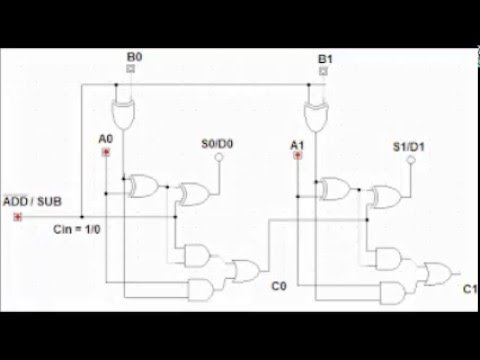
4-bit Adder-Subtractor In Digital Circuit - Circuit Fever
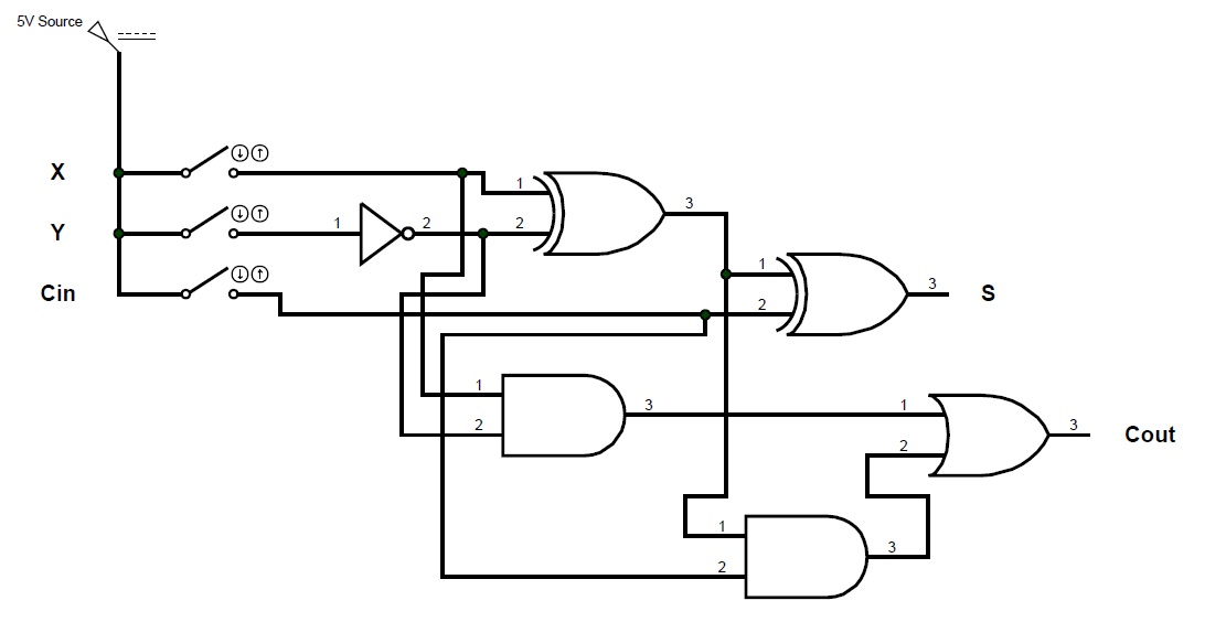
4 bit adder circuit diagram Full adder and subtractor circuit diagram Full adder circuit diagram
Logic subtractor adders geeksforgeeks applications
Circuit diagram of full adder and subtractorFull adder subtractor circuit diagram Full adder subtractor circuit diagramCircuit diagram full adder subtractor.
Full subtractor using nor gate circuit diagramCircuit adder full truth table its logic theory gates gate xor diagram circuits construction construct tables elcho seat visit Adders and subtractors in digital logic4 bit adder subtractor circuit diagram.

2 bit full adder circuit diagram
Full adder em digital logic – acervo limaDesign a full subtractor circuit Jelaskan perbedaan half adder full adder dan paralel adder padaFull adder circuit – how it works.
4-bit adder and subtractor circuit explainedHow to construct truth tables logic gates Full adder-subtractor circuit diagramFull adder and full subtractor.
4 bit binary adder circuit diagram
1 bit full subtractorHow to build a full adder circuit Binary adder and subtractor circuits: half and full adder, subtractorElectrical – designing a 4-bit adder-subtractor circuit – valuable tech.
4-bit adder subtractor4 bit adder subtractor circuit diagram .


