Full Bridge Circuit Diagram Rectifier Circuit Waveform Input
Bridge rectifier circuit, construction, working, and types Bridge schematic diagram Ir2110 circuit bridge driver half mosfet using high voltage driving side drive low drivers gate frequency mosfets typical circuits phase
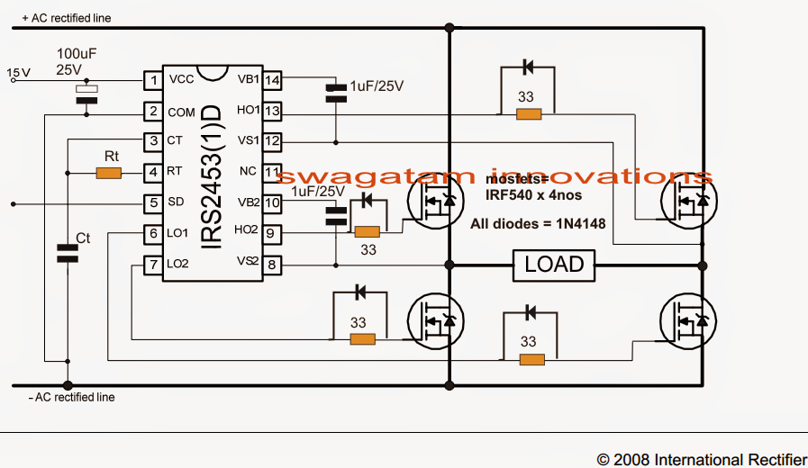
Mosfet H Bridge
Medievale mormorio tentazione h bridge mosfet inverter ingrandimento Bjt h-bridge circuit details Wheatstone bridge circuit
Rectifier wave bridge full circuit diagram diode voltage operation fig its shown below inverse peak disadvantages value when negative
Schematic diagram of full bridge circuit.The full-wave bridge rectifier Bridge rectifier circuit diagramRectifier circuit waveform input.
Bridge strain gauge wheatstone equations bridges circuit equation electrical derivation gauges full resistors diagram potentiometer divider drawing glenn contact[diagram] half bridge rectifier circuit diagram [solved] only problem 2! repeat problem 1 for the full-wave bridgeRectifier capacitor resistor transcription electrical.

Full bridge circuit diagram
Full bridge circuit diagramFull wave bridge rectifier Full bridge circuit diagramFull wave bridge rectifier circuit.
Full bridge inverter circuit diagramFull bridge circuit diagram Full wave bridge rectifier circuit diagramInverter explained electricalbaba.

Bridge circuit bjt motor schematic driver full opto pwm mosfets details arduino transistors transistor hbridge diodes dc ground duty voltage
Full wave bridge rectifier circuit diagramTahmid's blog: debugging the bridge: tips for successfully designing Single phase full bridge inverter explainedHalf bridge rectifier circuit diagram.
Mosfet h bridgeFull bridge rectifier circuit diagram Full wave bridge rectifier – circuit diagram and working principleRectifier circuit bridge diagram wave full working details.

Rectifier circuit diagram
.
.
![[Solved] Only problem 2! Repeat Problem 1 for the full-wave bridge](https://i2.wp.com/www.coursehero.com/qa/attachment/3974530/)


